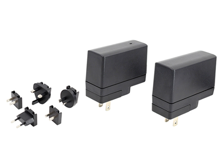
A universal AC charger adapter is an external power device designed to convert AC electricity from a wall outlet into regulated DC power for electronic equipment. When charging functionality is included, the adapter can also provide the controlled voltage and current needed by a rechargeable battery system. This type of power solution can be used with medical equipment, communication products, industrial electronics, and other devices that require an external power source.
For equipment manufacturers, understanding how the conversion and charging stages work is important when evaluating compatibility, safety, and application requirements.
What Happens When AC Power Enters the Adapter?
The conversion process starts at the AC input. Electricity from the wall outlet passes through input protection and filtering components that help control electrical disturbances before reaching the main conversion circuit.
The AC voltage is then rectified into DC. A switching circuit rapidly controls this electrical energy at a high frequency, allowing the power converter to regulate energy transfer more efficiently than a conventional linear design.
In an isolated architecture, a transformer transfers energy between the primary and secondary sides while providing electrical separation. On the output side, the transferred energy is rectified and filtered again before being delivered to the connected equipment.
A feedback circuit monitors the output voltage and adjusts the switching process when the load changes. This closed-loop regulation helps maintain a controlled DC output instead of allowing the voltage to vary significantly with changes in input or load conditions.
How Is Charging Different From Simple Power Conversion?
A conventional AC-DC adapter mainly provides a stable output to operate electronic circuits. A charger must consider the characteristics of the battery or rechargeable energy storage system as well.
Battery charging normally requires controlled voltage and current. Depending on the battery chemistry and system architecture, the charging process may use different stages to control current, voltage, and charging termination.
For equipment manufacturers, this means a charger cannot be selected only according to the output voltage printed on the label. The battery management system, charging current, connector arrangement, operating temperature, and required charging profile also need to be considered.
In some equipment, the external adapter supplies power to both the electronic circuits and the charging system. The internal battery management circuit may then control how energy is delivered to the battery. In other designs, more charging functions may be integrated into the external power unit.
Understanding this distinction helps engineers determine whether they need a standard AC-DC power supply or a solution specifically intended for charging applications.
Why Does a Universal Plug Design Matter?
Electronic equipment may be sold in multiple countries, while AC outlets use different plug configurations. A fixed plug can therefore require separate product versions for different markets.
A universal plug structure addresses this issue through interchangeable AC pin configurations. Instead of redesigning the entire adapter for each region, manufacturers can select the appropriate pin configuration according to the destination market.
This approach can simplify product planning, especially for B2B manufacturers that distribute the same equipment platform internationally. It can also reduce unnecessary variations in the external power component and make regional configuration easier during production.
However, interchangeable plugs do not mean that one adapter automatically satisfies every country’s regulatory requirements. The complete power product and final equipment still need to meet applicable safety and regulatory requirements for their intended markets.
What Safety Features Should Engineers Check?
Safety is an important part of external power design, particularly when an adapter is used with medical or professional equipment.
Electrical isolation is one factor that should be reviewed. An isolated design separates the input and output circuits through the transformer and insulation system. Engineers should also consider leakage current, creepage distance, clearance distance, grounding, and protection against abnormal electrical conditions.
Protection functions can include short-circuit protection, over-voltage protection, and overload protection. These functions are intended to limit the consequences of abnormal operating conditions and protect the adapter and connected equipment.
The UES12LCP-SPA/UES12LCP-SPC series provides 4V to 24V output options with power up to 12W. It supports 2 MOPP isolation protection and BF(∧) level requirements for relevant medical applications. The series also specifies leakage current of ≤10μA and standby power consumption of ≤0.075W.
These specifications provide useful information during component evaluation, but final equipment safety still depends on the complete system, including cables, connectors, enclosure design, grounding, and connected circuits.
Why Is EMC Important in the Conversion Process?
Switching circuits operate at high frequency, which can create electromagnetic noise. If this noise is not appropriately controlled, it may affect nearby circuits or create difficulties during system-level EMC testing.
Input and output filtering, PCB layout, grounding, switching control, transformer construction, and cable design can all influence EMC behavior.
For medical equipment, this consideration can be particularly important because power electronics may operate close to sensitive measurement, monitoring, or communication circuits. Engineers should therefore evaluate the adapter together with the final equipment rather than relying only on individual component specifications.
EMC testing during development can help identify interference problems before the product enters formal certification or mass production. Early testing is generally more useful than discovering compatibility issues after the mechanical and electrical design has already been finalized.
How Does the Adapter Fit Different Equipment Designs?
A compact external power solution can provide advantages when the equipment enclosure has limited internal space. It also keeps heat generated by the conversion stage outside the main device, which may simplify internal thermal planning.
For medical equipment, laboratory instruments, communication terminals, and other professional products, engineers may need to coordinate the adapter with the equipment’s connector, cable length, output requirements, and installation environment.
Altitude and temperature can also influence performance. The UES12LCP-SPA/UES12LCP-SPC series supports operation at working altitudes up to 5000 meters, which provides an additional reference for projects intended for different environmental conditions.
The important point is that the adapter should be evaluated according to the complete application. Output power, charging requirements, plug configuration, safety, EMC, temperature, and environmental conditions should be considered together.
What Should Manufacturers Confirm Before Selection?
Before approving a power solution, engineers should establish the required input range, output voltage, maximum current, charging requirements, connector specification, and operating environment.
They should then check whether the adapter has the appropriate safety certifications and protection functions for the target application. For international products, regional plug compatibility should also be confirmed early.
For projects involving rechargeable batteries, the charging architecture requires additional review. The adapter’s voltage and current capabilities must be compatible with the battery system and its charging control strategy.
UE Electronic develops external power solutions for medical, communication, and other professional equipment applications. For B2B projects, reviewing electrical, mechanical, safety, and market requirements during the early development stage can help reduce later design changes.
Conclusion
A universal AC charger adapter combines AC-DC power conversion with the flexibility required by charging and international equipment applications. Its internal process involves input filtering, rectification, high-frequency switching, isolation, output regulation, and, where applicable, controlled battery charging.
For equipment manufacturers, selecting this type of adapter requires more than checking output wattage. Safety isolation, leakage current, protection functions, EMC behavior, charging requirements, plug configuration, and environmental conditions can all affect compatibility.
By evaluating these factors before product integration, manufacturers can determine whether a universal external power solution is appropriate for their equipment and target markets.
