Signal interference can cause missed reads, duplicate records, and inaccurate material tracking in factories. These problems often appear around metal machinery, busy production lines, and storage areas with dense tagged goods. However, not every reading failure comes from radio interference. Poor antenna placement, unsuitable tag selection, and incorrect reader settings can also affect performance. Factory operators need to identify the cause before changing equipment or adjusting power. A structured approach helps reduce unwanted reads, improve tag detection, and keep production records consistent. The following methods explain how to prevent common reading problems in industrial environments.
Understand What Causes Reading Problems
Metal surfaces are a common challenge for UHF RFID installations. Machine frames, steel racks, and metal containers can reflect radio waves and change the reading pattern around an antenna. Tags attached directly to metal may also perform differently from ordinary labels. In these situations, installers should check the tag type, mounting position, and distance from nearby structures.
Wireless activity is another factor to investigate. Multiple RFID systems operating close together may create overlapping reading zones or radio interference, depending on their configurations. Other wireless devices may also affect the local radio environment. A site survey can help technicians identify active equipment and distinguish radio-related problems from weak tag signals or poor coverage.
Factory operations can change the reading environment throughout the day. A production line may perform differently when loaded with metal components than when running empty. Moving vehicles, stacked pallets, and temporary storage racks can also alter tag visibility. Testing under normal operating conditions gives engineers a more accurate basis for prevention.
Control the Reading Zone Through Antenna Placement
Antenna positioning is one of the first areas to review when tags are detected outside the intended zone. When installing UHF RFID Readers, engineers should consider the direction of tagged items, the distance to the reading point, and the location of nearby metal structures. Antennas should face the intended tag path rather than cover a broad area without a clear purpose.
For conveyor systems, antenna placement should match the width of the belt and the expected position of tagged goods. If tags face away from the antenna, detection may become inconsistent. Testing different antenna angles and positions can reveal a more suitable arrangement. Where metal products pass through the reading point, engineers should also assess tag placement and use tags designed for the application.
Warehouse entrances require similar planning. Antennas positioned on both sides of a passage may help detect tags on differently oriented pallets. However, excessive overlap between adjacent reading zones can produce unwanted reads. Technicians should test each antenna separately before evaluating the combined arrangement. This process helps locate coverage gaps and reduces unnecessary overlap.
Adjust RF Power to Match Site Conditions
High RF output does not automatically produce better results. Excessive power can extend the reading zone into nearby storage locations or production areas. The reader may then detect tags that have not yet reached the intended checkpoint. Lowering the output may help control this problem, provided the target tags remain within reliable reading range.
An industrial UHF RFID reader should be configured according to the physical layout and operating requirements of each reading point. Engineers can begin with a moderate power setting, test known tags, and increase or decrease the output in small steps. They should record missed reads and unwanted detections after each adjustment rather than changing several settings at once.
The required configuration also depends on movement speed and tag density. A fast-moving conveyor may need a different setup from a fixed asset inventory station. Where multiple readers operate nearby, technicians should review their reading zones and operating configurations together. Any coordination method must be supported by the selected equipment and system design.
Choose Hardware That Supports Practical Deployment
Hardware selection should reflect the actual factory environment. Buyers comparing UHF RFID Readers need to review antenna interfaces, RF output adjustment, compatible tags, installation requirements, and integration needs. The advertised reading distance is only one consideration. Actual performance depends on the antenna, tag, mounting conditions, surrounding materials, and site configuration. For a broader selection framework covering read range, antenna ports, connectivity, and operating conditions, see RSTC’s UHF RFID reader selection guide.
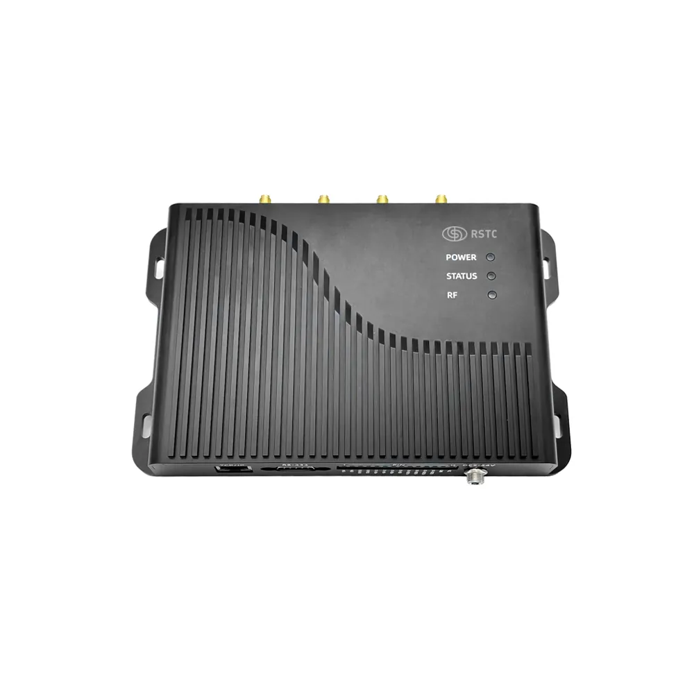
For applications that need several antenna positions, the RS-F905 Four-Port UHF RFID Reader from RSTC provides four external antenna ports with SMA interfaces. Powered by the Impinj E710 chipset, it supports passive UHF RFID tag identification and offers adjustable RF output. These features give installers options for arranging reading points around production lines, warehouse entrances, and storage areas.
The RS-F905 supports a reading distance of up to 25 meters when paired with suitable UHF RFID antennas and tags. This specification can inform initial planning for warehouse operations, production lines, asset tracking, and parking management. It should not be treated as a guaranteed distance in every factory. Site testing remains necessary to determine suitable power levels, antenna positions, and practical reading boundaries.
Test for Interference Before Production Starts
A controlled test helps identify whether a reading problem comes from interference, poor coverage, or tag placement. Technicians can begin with a fixed group of tags and record the number detected at a defined position. They should repeat the test at different distances and tag orientations, then compare the results. A consistent test procedure makes changes easier to evaluate.
The next step is to introduce real operating conditions. Run the conveyor, move representative loads, and operate nearby machinery as they would during normal production. Check whether unwanted reads occur outside the designated zone. If the problem appears only at one position, inspect nearby metal structures, antenna direction, cable connections, and overlapping coverage before making broader changes.
When several readers are installed close together, test each unit independently and then operate them together. This can reveal whether a problem occurs only when neighboring reading points are active. Engineers should document the configuration associated with each test, including antenna positions and output settings. This record helps the team repeat successful tests after installation changes.
Keep Performance Consistent as the Factory Changes
Interference prevention should continue after commissioning. New machinery, relocated racks, altered conveyor paths, and changes in product packaging may affect radio performance. After a significant layout change, operators should repeat key reading tests and compare the results with the original baseline.
Routine inspections should cover antenna mounts, connectors, cables, and tag attachment points. Staff should also review recurring missed reads and unexpected detections instead of assuming that every problem requires higher RF power. A clear fault record can help maintenance teams identify whether the issue follows a particular location, product type, or operating condition.
Reliable RFID performance comes from matching hardware configuration to the factory environment. Careful antenna placement, controlled RF output, appropriate tags, and repeatable testing can reduce unwanted reads and improve identification consistency. When evaluating an industrial UHF RFID reader, project teams should prioritize verified performance under actual operating conditions rather than relying on specifications alone. With a documented installation plan and regular checks, factories can maintain more dependable tracking across production and warehouse operations. RSTC offers the RS-F905 as an option for projects that require four antenna connections and adjustable RF output, while final system performance should be confirmed through application-specific testing.
